Matched filter simulator
This simulator was developed as part of the Ardumower project. It allows you to try
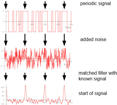
out the matched filter (aka optimum filter) with pre-defined (or your own) sample signals, to add noise to it and finally apply a matched filter against the generated (noisy) signal and your samples.
Quick start (you can find more detailed instructions at the bottom)
1. Choose an input signal (slider 'Example signals' at the right), e.g. choose 'pseudonoise4_nrz'.
2. At the left top graph, you can see the generated signal and at the left bottom graph, you can see the matched filter output.
3. Now increse noise amplitude to 2.0 (slider 'Noise'). You can see how the filter still detects your samples.
Signal (optional FIR-filtered, amplified)
FFT
Matched filter
Signal workflow
The signal is generated by the samples that you define. Noise is added. Optionally, an FIR filter is applied. Finally the matched filter is applied.
Samples + Noise => FIR filter => Signal (optional FIR-filtered, amplified) => Matched filter (against samples)
Help
Graph Signal: shows the signal you defined by your signal samples, including any added noise, optionally FIR-filtered
Graph FFT: shows the frequency spectrum of the graph signal
Graph Matched filter: shows the matched filter output
Slider Example Signal : allows you to choose a pre-defined signal (signal samples)
Slider One sample width: allows you to set the width of one sample
Slider Noise : allows you to increase/decrease the added noise amplitude
Slider Example filter: allows you to choose a pre-defined FIR filter
Slider New filter bandpass start/stop: allows you to generate a FIR bandpass filter
External links:
(1) Matched filter theory (German)
(2) More explanations on the matched filter and this simulator.
(3) Sound card-based oscilloscope (includes matched filter)
(4) Video explaining the matched filter visually.
(5) Matched Filter in der Nachrichtentechnik.
(6) FIR filter design
(7) Matched filter in Java
Algorithm (C code)
    // matched filter (correlation filter)
    // H[] holds the samples to match,
    // M = H.length (number of samples in H)
    // ip[] holds ADC sampled input data (length > nPts + M )
    // op[] is matched filter output buffer
    // nPts is the length of the required output data
    void corrFilter(int8_t *H, int16_t M, int8_t *ip, int16_t *op, int16_t nPts)
    {
      int16_t sum = 0;
      for (int16_t j=0; j < nPts; j++)
      {
        sum = 0;
        for (int16_t i = 0; i < M; i++)
        {
          sum += ((int16_t)H[i]) * ((int16_t)ip[j+i]);
        }
        op[j] = sum;
      }
    }


    // optimized version using pointers
    // returns: min or max, depending on what is (absolutely) higher
    int16_t corrFilter(int8_t *H, int16_t M, int8_t *ip, int16_t nPts){
      int16_t sumMax = 0;
      int16_t sumMin = 0;
      for (int16_t j=0; j < nPts; j++)
      {
        int16_t sum = 0;
        int8_t *Hi = H;
        int8_t *ipi = ip;
        for (int16_t i=0; i < M; i++)
        {
          sum += ((int16_t)(*Hi)) * ((int16_t)(*ipi));
          Hi++;
          ipi++;
        }
        if (sum > sumMax) sumMax = sum;
        if (sum < sumMin) sumMin = sum;
        ip++;
      }
      if (sumMax > -sumMin) return sumMax;
        else return sumMin;
    }